Over the previous weekend, I finally got around to designing the first STM32 board that would allow me to play around with USB, and practice PCB design. I tried to make the design simple whilst testing a few features
- Single Wire Debug Interface
- Basic USB communications
- UART Communication with LED Indicators
- External crystal oscillator (HSI)
- General Purpose IO
I planned the board to talk to STM32MP157F-DK2, which is a Raspberry Pi-like single-board computer that would change the LED output on my board. It would look something like this:
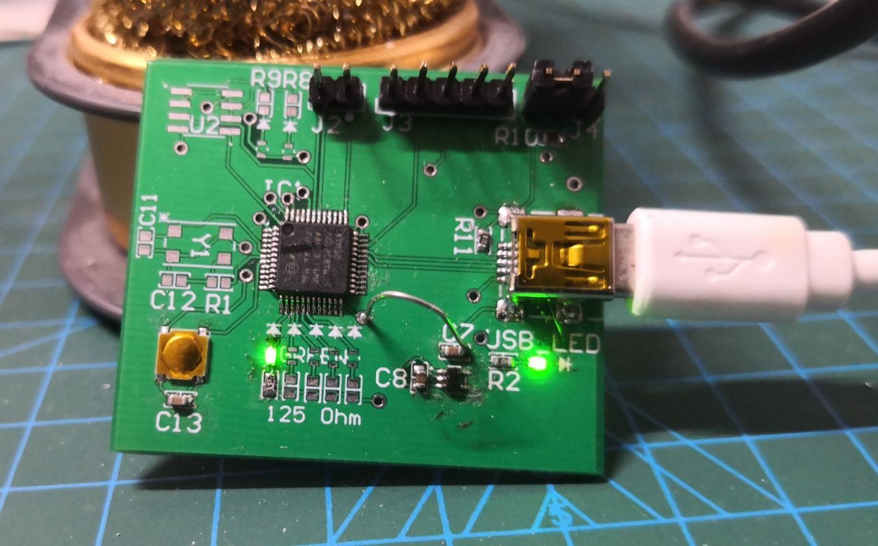
Yesterday, after hours of suffering, the board got soldered. Not all of the components are present, the first prototype works!
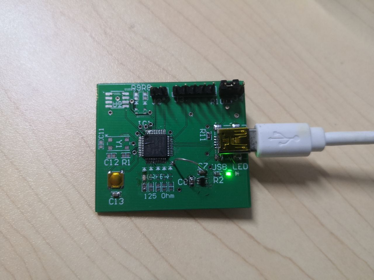
The good: the board works! I programmed it using another STM32 microcontroller. Everything draws an appropriate amount of current. The LED shines well despite being a tiny 0603 component.
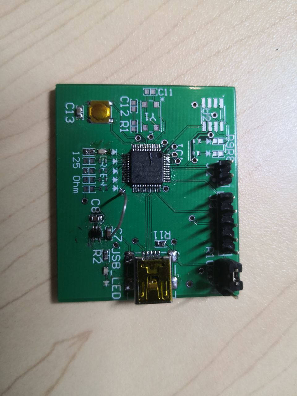
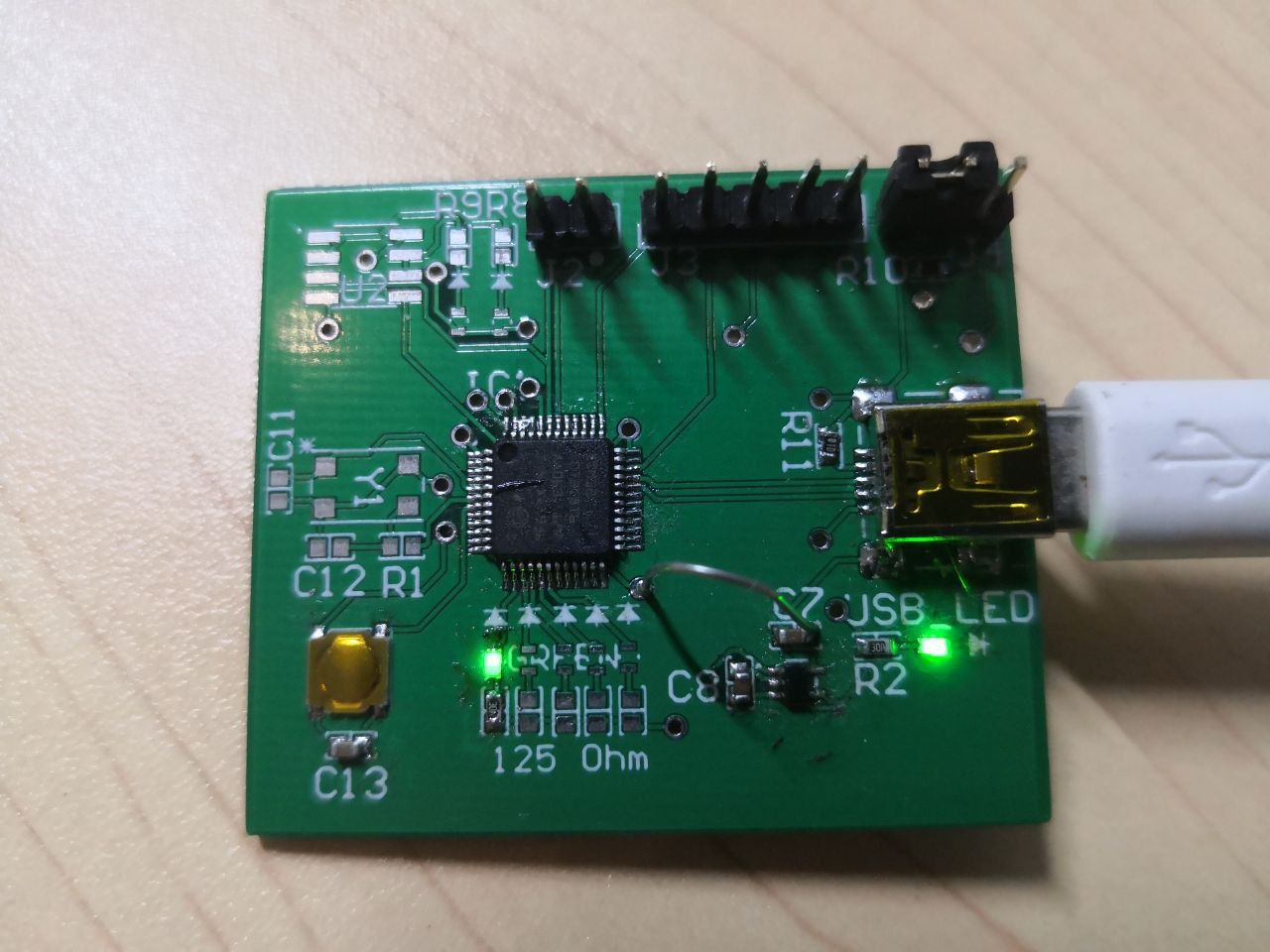
The bad: the only mistake I made was mislabelling the net during the design process, which failed to connect the output of the regulator to the rest of the power net. Had to hack on a wire to connect fix that.
The ugly: soldering 0603 components is often challenging and does not result in the best visual experience. Going further, it may be a good idea to switch some 0603s to 0805s if space is not an issue. Also, the footprint for the pins was not chosen correctly and was not spaced correctly. Ended up with uneven pin height. It works but it ain't pretty.